 FleetMesh
System architecture
Design around clear boundaries.
Separate the decisions made across a fleet from the interfaces carrying them and the systems executing them.
A conceptual fleet system
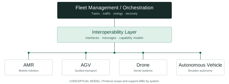
Three questions, three boundaries
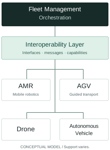
This is FleetMesh's conceptual model for organizing engineering questions. It is not a reference implementation, a universal protocol stack or a description of a FleetMesh product.
Locate the VDA 5050 boundary
The VDA 5050 interface sits between fleet control and mobile robots. Interfaces to external IT and infrastructure equipment are outside the recommendation's scope. Connecting a warehouse system, door or lift therefore needs its own interface agreement; support cannot be inferred from the robot's VDA 5050 claim.
Source: VDA 5050 v3.0.0, section 2.
Observation is not command authority
MassRobotics provides a shared information model for robot interoperability, rather than replacing each vendor's fleet management. A system consuming shared robot status must separately establish whether it has any authority to assign tasks or change behavior.
Source: MassRobotics' scope explanation. The authority boundary is FleetMesh's engineering interpretation.
Write an interface agreement
For each connection, record the producer, consumer, schema version, timing assumptions and failure behavior. For each decision, name the component that owns it. Record any adapter's translation rules and information loss explicitly.
- Identity: how a physical system maps to protocol identifiers.
- Coordinates: which frame and map each position refers to.
- Capabilities: what the receiving system can actually do.
- Failure: what a timeout means and who may initiate recovery.
FleetMesh design recommendations. Drone and road-vehicle examples need domain-specific interfaces and separate validation; this site makes no cross-domain compatibility claim.